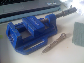
Part one of the beak insert is complete. Just need to wait for part 2 to be made before i can integrate the solenoid and insert it in the wood:
Wednesday, 31 March 2010
Sanding
Engineering
Monday, 29 March 2010
We love sleep
Dr Neil Stanley featured on a radio show on Radio Sheffield to campaign for sleep to be taught in schools as well as providing information on sleeping well.
Sunday, 28 March 2010
Making a beak
Thursday, 25 March 2010
Log #2.5
So for the past 2 weeks, I have been working hard on perfecting my log model. A few things have changed along the way visually and mentally...
First thing you should know is that there is a method and order to which things must be done. This was only discovered through practice from working various logs.
Second thing you should understand is that finding the center point is crucial to the design and is the hardest thing to achieve due to an uneven edge, unsymmetrical semi circle which gives 2 different diameters at opposing ends and one flat edge (also hard to get right).
Third thing you should understand is that the tools can be limiting. This ranges from drill sizes and depth a hole can be drilled. From practicing i altered my design to work with these limits rather than working against them.
Fourth thing i hope you realize is that every cut and mark on the wood is important that i was unable to take photos of every sequence.
So without further to do, here is a wee steep by step introduction to my model:
The image below shows the trunk section i have chosen to work with. This is immature baby elm so has a pixelated grain and rough silver bark.
Before just cutting in half, careful consideration towards edge, quality of bark and terrain need to be taken into account for positioning of design features. I used masking tape to outline my 2 halves to confirm my decisions.
To get the best, vital flat edge i wait for new blades in the workshop to be installed. I use the band saw and guide the wood through by holding onto and leaning on 2 other square pieces of timber at either side of the log. Saw at a slow and steady pace.
Find the center point by measuring each edge with a ruler to find half way point of that edge. Use a set square to align them up via the flat edge and go around the log. Keep measuring, checking and altering your middle point. I found that i was only satisfied with the center point when i could find no alterations. This will take a long time but if done wrong, you need to start again or undertake drastic action.
(I had the pleasure of taking such drastic action when it became apparent that i was 5mm out with the alignment of two features. A clever technique i will share later on!)
After plenty of trials and errors to align my dial and beak insert, the simplest way is to measure and cut a template (square bit of MDF) to the exact height i wanted to drill and marked it on both opposing center points.
Once drilled, the hollowed out section meets the drilled beak insert:
I have 2 platforms and a hole that meets the drill section to still provide support to the brass inserts.
To cut the slant, the button hole needs to be drilled on a flat surface and the bark protected with masking tape. Through trial and error, i cut at a 33.3 degree angle.
This is an image of one of my earlier tests that cut through a knot. I made sure my final one did the same as without it is not as special:
I then drilled holes for the toggle switches and installed them by reducing the wall thickness and expanding the hollowed section.
So this is where i am at. I need to install the electronics(even thought the toggle switches are in place, they are not connected as they are there to stop the holes reducing in size as i have discovered, happens) and install the brass parts.
I am still deciding my brass push button as it well depend on the button i finally decide on once i have found a click i like. Sadly online shops don't have a mp3 on these...
Wednesday, 24 March 2010
Related article
An article; "Getting ready for bed" from "NHS choices" provides suitable night time rituals to help you get your sleep rhythm back on track, published 14.03.10.
The ONE show
The ONE show, (23.03.10), showed a 10 min documentary about body clocks and the importance of getting enough sleep and having and maintaining a sleep rhythm. The research from prof. Debra Skene is about health risks of not getting enough sleep that she has linked it to cancers and heart related problems. The documentary was presented by Dr Phil Hammond.
I am hoping to contact the ONE show, Dr Phil Hammond and prof Debra Skene about my project. The ONE show is also recruiting Brits to take part in their 7.30 hours of sleep a night experiment to see how they feel.
Tuesday, 23 March 2010
Tim
We had a man from Nokia gave us a short and sweet presentation and then come round and looked at our work. Tim was very nice and seemed very impressed by my work and in particular the solenoid imitating a woodpecker.
Nokia is providing a summer internship that I hope to apply for.
Stefano Mitri
Stefano came round and personally spoke to me about my final year project.
He liked my idea and could understand why i have chosen to make my product from a log. In fact he really liked my move away from plastic and into something quite organic. His only comments were about the technology and how he would prefer to see the electronics rather than hiding it in the wood. This was one of my previous ideas that i chose to put to one side only so i could progress and make something. I do plan to go back to it even more now!
His closing statements to me was that he would forget my name and my face, but he would remember the wood...compliment? Insult? I'll let you decide.
Sunday, 21 March 2010
Brass parts
Brass parts
Monday, 15 March 2010
Headline news
Glasgow teachers are teaching teenagers how to sleep and find a sleep pattern to increase their amount of sleep a night. Click here for full article.
I might be onto something here!
Time dial
Sunday, 14 March 2010
Logo Type #1
This is an example experimenting with a possible name and presentation of logo:
My aims:
My aims:
Continuation with Log #1
Thursday, 11 March 2010
Visual Practice
After making many sketches and working on Pete's feedback i decided i could only really confirm my idea by completing a quick visual model, lucky i did too!
So i took one of my logs and chopped it to size and cut it in half;
I drilled in holes where the beak would be;
and carved in both halves the detailing i had chosen to do;
This is the result;
Not too keen after all that! My issues is with this feature shown. I like the shape of the log and the fact that it is cut in half. I think i would make the product a little longer in my final model as well.
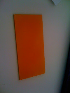
I like the bark but i feel my product is backwards. All my efforts are going around my main and important feature, the woodpecker imitator which is located at the back of the device. Should i once again try and bring a physical woodpecker to the front or try woodpecker features??
Bringing a physical woodpecker to the front brings many problems. Does the beak hit of the log, which will not amplify sound but will dampen it or perhaps the beak is at the front but fits right through to the back still hitting of different materials? I know power and support will be massive and tricky to get right.
I would want to do this as the range of sounds that could be potentially produced by the user are so vast and pleasant, it would almost destroy the product if it was unable to do so.
After struggling to come up with new designs with the woodpecker imitator at the front but still able to hit the back, i began to question why i was so determined to even have a visual of the bird.
If you can hear the bird and sense a bird presence, an actual bird may be too much.
As a result i am now making the front with the time dial, which i usually think of as a back, as a front. I am adding the woodpecker hole to go around the dial, and have the dial to contain features of the birds beak i.e. a taper similar to the beaks. The back will now act like a back. The bird hole will be a mechanically made, so not natural and will be made from brass.
I am hoping that the front of the device will look convincing and pleasant to look at, almost as if that would be it and once the product, at closer inspection, is turned around and played with, the mechanical sound would be unexpected and the mechanics would be a nice surprise.
Presentation Boards
I admire the style, emotion and layout of CookIn Table presentation boards even though i dislike the idea...
I especially like the features board.
Wednesday, 10 March 2010
PCB Making
Once happy with the layout of my PCB boards, it is time to laser cut onto single sided copper board. I followed this instructable.
My brief wee summary:
1. cover the copper side of the board in spray paint.
2. Getting the PCB board ready for laser cutting;
The laser cut cuts away the spray paint exposing the copper. The tracks remain concealed under the spray paint.
4. Acid bath*
*this will remove the exposed copper, leaving the spray paint alone.
2. add warm water to the surroundings to quicken the procedure.
5. return to the basin every 15 mins to wash the PCB boards with an acid soaked sponge. This helps to uplift the exposed copper. (this takes a couple of hours to do)
6. Once all the exposed copper is removed, rinse the PCB board under water and remove the with hot water.
7. drill the holes
8. add and solder the components.
My brief wee summary:
1. cover the copper side of the board in spray paint.
2. Getting the PCB board ready for laser cutting;
- export and save your fritzing file as a etching PDF.
- open photoshop
- draw a black box over your PCB and invert the wiring, ctrl i
- save as jpeg
- open illustrator
- save as illustrator file
The laser cut cuts away the spray paint exposing the copper. The tracks remain concealed under the spray paint.
4. Acid bath*
*this will remove the exposed copper, leaving the spray paint alone.
- add acid to a small plastic container inside a larger basin.
2. add warm water to the surroundings to quicken the procedure.
5. return to the basin every 15 mins to wash the PCB boards with an acid soaked sponge. This helps to uplift the exposed copper. (this takes a couple of hours to do)
6. Once all the exposed copper is removed, rinse the PCB board under water and remove the with hot water.
7. drill the holes
8. add and solder the components.
Subscribe to:
Posts (Atom)